Ask Latest Price
Video Channel
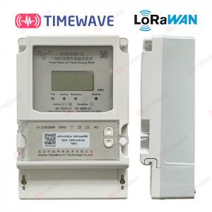
Brand Name :TimeWave
Model Number :Type DTZY2397
Certification :ISO/IEC 20000-1,ISO/IEC 27001,ISO/IEC 9001
Place of Origin :Hubei , China
MOQ :Negotiable
Price :EXW price US$ 60-120/ set
Payment Terms :L/C, T/T
Supply Ability :2000 sets per week
Delivery Time :3-5 weeks after receive the payment
Packaging Details :Each piece is packed in one carton, 10 sets per carton
Name :Lorawan IoT Smart Electric Energy Meter
Material :Plastic
Communication Protocol :DL/T645-2007
Color :Off-white
Structure :Wall Mounted
Function :Active upload/two-way transparent transmission
Product :Single/Three phases smart energy meter
Customization :OEM/ODM
Standards :IEC62053-21, DL/T645-2007
Rated voltage un :220V/3*220v/380v
Power grid frequency :50Hz
Operating voltage :80% Un ~ 115% Un
Rated current limit ib :5A
Maximum current: Imax :80A/100A
Starting current :0.4% Ib
Connectivity Protocol :NB-iot/LoraWan
more